This article explains how to install a DC-DC charger.
We have a separate article that explains the installation of a cut-off or change-over relay for your charger here.
A DC-DC charger is sometimes called a Battery-to-Battery or a B2B charger … it’s basically the same thing.
This particular Victron DC-DC charger is our go-to for most installations in a Motorhome/Campervan. It is a non-isolated model rated at 30A (12v in and 12v out).
This non-isolated model uses the chassis as a common ground or negative.
Very similar to the non-isolated, this is the isolated model, mostly used on boats where the hull cannot be used as a common ground or negative.
On a vehicle you can simply bridge the two negative terminals.
You’ve probably just bought a Lithium (LiFePO4) battery. Some “experts” tell you to just slap it in and the BMS will protect it. Others have said you must install a DC-DC charger (otherwise known as a battery-to-battery or B2B charger). In this article we assume you’ve decided to install a DC-DC charger (we won’t go into the pros and cons here).
We also won’t go into the details on how to install a cut-off or change-over relay, that can be found here.
Nomenclature
Before we dive into things lets just clear up some nomenclature.
EBL - this is your “Electro-block”. By Electro-block we mean the box of electric components with a bunch of wires of different colours (red, black, blue, yellow, bown, etc) coming in and out (some thick-ish and some thin). It probably also has a bunch of blade fuses. It’s probably tucked away in one of your lockers or in the garage.
Wire vs Cable - when do you call a wire a wire and a cable a cable? Conventional definitions don’t really work for us in this context. Strictly speaking a wire is a single conductor whereas a cable is a group of conductors. Generally speaking we think of a cable as being something thick and a wire as something thin. However, to keep it simple from now on we use the word “cable” for everything.
SOC - is the State of Charge, measured as a percentage of 0% to 100%.
Positive - the positive terminal of a battery or device, we install red but factory builds may vary in colour according to country.
Negative or Ground - these two terms are interchangeable and basically the same on a DC system. Often black but the colour may vary according to country. In this document we’ll refer to “negative”.
D+ - this is how the alternator tells any/all electrics that the engine is running. It’s a “thin” cable coming off a connector on the alternator that has +12v when the alternator is running. Most motorhomes and vans have one or more D+ cables coming to the habitation electrics.
VSR - Voltage Sensing Relay. The relay is activated when it detects a voltage that shows the engine is running (as opposed to being activated by D+)
So let’s talk about the DC-DC charger …..
Standard motorhome with an EBL
In this next image we’re looking at a standard from-the-factory motorhome. It has an elementary split-charge system as part of your EBL. Note that some motorhomes have some form of a DC-DC charger or at least a way to “condition” the power going into the leisure battery (particularly more modern and/or expensive rigs). In the image we have a very simple relay that effectively places the two batteries (starter and leisure) into a parallel configuration.
The black negative cables usually (or often) simply go down to the nearest accessible place on the chassis. The red positive cables go from the starter battery to the EBL via the chosen route of the manufacturer, quite often through the “false floor” or down along the chassis in conduit. Our diagram make it look like the red cable goes up and then back down, that’s just to make it easier to visualise.
It’s very common to find relatively thin positive cables running from the starter battery to the EBL, 6mm² or less. More modern motorhomes often have thicker cables. More on that later.
Unless your existing positive cable running from starter to EBL is thick (at least 10mm) you’re going to want to run a new one. In the image below we run a 16mm (or at least a 10mm) all the way from the starter battery to the DC-DC charger. We’re know that the cable running from the alternator to the starter battery will be thick (standard base vehicle build has a good cable).
We’ve now run a new cable from starter battery to DC-DC charger and connected it to the +IN terminal which on the Victron DC-DC is on the LEFT as you face the unit . We’ve also run a new cable either directly to the battery +Terminal or to a +bus-bar (either method works as long as the whole chain of cables is decent thickness).
IMPORTANT: At this stage you will need to be thinking about a way to prevent two different and disparate systems from charging the same battery. You will probably want to consider installing a cut-off or change-over relay, which is covered here.
Van conversion or motorhome without an EBL
The simple van conversion below shows us a Split Charge Relay (quite often a Voltage Sensitive Relay or VSR). Your conversion may not yet have a split charge relay if you're in the early stages of a conversion. The relay may be activated in a number of ways:
from D+
from ignition
by detecting charging voltage (VSR).
The DC-DC charger replaces the split-charge system - once the DC-DC charger is installed there is no need to keep the original Split Charge Relay (or VSR) in place. This makes it an easier install, an existing EBL complicates things because you need to add a cut-off or change-over relay. This is covered here
Usually the DC-DC charger doesn’t fit in where the split-charge relay was located. It’s much bigger and needs to be able to cool itself (must be mounted so the cooling fins allow convection).
Choosing cables to run from starter battery to DC-DC charger
Let’s assume you’re going to run a 3m long cable from the starter battery to the new DC-DC charger. If your distance is much longer you will need to compensate. The “average” length of cable we run is 2-3m. We’ll assume around 1m from the DC-DC charger to the leisure battery, and the same goes for the negative cable.
The cables running to the DC-DC charger from the starter battery shown above should be reasonably thick, 10mm² at the very least. We prefer to go with 16mm² for our recommended Victron 30A model just to future-proof and reduce heat buildup. The Victron 30A model can pump a maximum of 30A into the battery, but to achieve this it may draw a little more from the alternator if it’s voltage is a bit low (in our experience up to around 33A). The DC-DC charger often takes a slightly lower voltage and increases it to 14-ish to charge the LiFePO4 battery, this may come as a shock but in our experience more modern alternators often run at a slightly lower voltages than older alternators.
Wire sizing apps will tell you that 10mm is fine for a 33A draw based on cable capable of up to 60°C, but in reality 60°C is actually quite warm. In fact, a 10mm² cable can handle up to around 40A based on a cable temperature of up to 60°C. However, we prefer to keep it lower and therefore when we install new cables will attempt to go for 16mm².
When the need arises we will reluctantly use an existing 6mm cable because such a cable can handle 33A if it is allowed to heat to 75°C. Just for interest, cable sizing is affected considerably by the jump from 60°C cable to 75°cable. Think of it as the cable going from being a bit warm to slightly hot. This is not usually a problem as good quality cable has insulation rating of 200°C or at the very least 150°C, so 75°C is half of what the insulation is capable of.
But to keep it simple … suggest you buy some good quality 16mm² cable.
The red (positive) cable running from the DC-DC charger to the battery is often about 1m and easy to replace if necessary so going with 10mm² is fine, but seeing as you’re buying 16mm² cable stick with that.
The same goes for the black negative cable.
Connecting cables to the DC-DC charger
The Victron DC-DC chargers can take a maximum of a 16mm² cable. If you’re using 25mm² cable you’ll need to reduce it - cut off a few strands until it fits.
The cables go in here:
IN+ is the positive cable from your starter battery
GND is the black negative cable bolted to your chassis or to a bus-bar
OUT+ is the outgoing positive cable to your leisure battery (or to a bus-bar connected to your leisure battery)
Remote H can be connected to your D+ or the L & H can be bridged as shown below (more on that under “DC-DC Charger Activation”)
We strongly suggest you use ferrules or pin connectors on your cables.
The round 16mm² ferrules don’t actually fit into the DC-DC connectors until you crimp them, at which time they become square shaped and then fit in nice and snug.
Notice the green “remote” plug on the left. The image above is the default configuration which means that the DC-DC charger is activated purely by voltage. More on that below.
DC-DC Charger activation
If you leave the Remote L & H bridged as shown in the image above the DC-DC charger will be activated purely according to the voltage of the starter battery.
If you wish to activate the DC-DC charger by D+ you will need to remove the small black wire on the green Remote connector and feed the D+ into the H terminal (Right hand connector). The D+ is only a “signal” so very low current, therefore a thin cable can be used. We generally use a 1.5mm cable.
In the next section we’ll describe how to find D+
IMPORTANT: if you choose to activate the DC-DC charger entirely by voltage of the starter battery you will need to ensure your settings work for your particular vehicle and setup. There is no one-size-fits all as it depends on your particular alternator and thickness/length of cable. Even if you know if you have a Smart vs Standard alternator your particular setup may not work with those standard settings. We explain how to get into the app later on, but the area you need to be focussed on is the “Engine Shutdown Detection” and in particular the “Start Voltage”
In the image above the person has a Smart Alternator which comfortably reaches the Start Voltage (14v) after a minute or so, thereby activating the DC-DC charger effectively.
The only way of knowing what your Start Voltage should be is to test your rig. You’d be surprised how many Smart alternators run at a relatively low voltage. This is one of the reasons we prefer to activate the DC-DC charger by D+ … no more guess work.
IMPORTANT: changing the Start Voltage automatically changes the remaining three parameters. The collection of these four parameters can affect the rate of charge, so if your alternator runs slightly low the DC-DC may have been activated but then charges at a lower rate than you’d expect. Most of our installs have a lower Start Voltage and we use D+ to activate the charger, when using D+ our preferred Start Voltage is 13v
NOTE: if you choose to activate the DC-DC charger via D+ then BOTH of the following must be true for activation:
D+ must have +12v
The Start Voltage must have been reached
If you’ve left the Remote connectors bridged then only the Start Voltage must have been reached to activate the charger.
victron connect app
Download and install from the App Store or Google Play. You will need to answer in the affirmative for the things Victron Connect wants access to (Bluetooth, location, etc).
Once you have installed the app and opened it, you will see a list of Victron devices. Your Orion will be named something like this.
While loading the device you will be asked for the PIN, it’s printed on your box (and is probably not 000000)
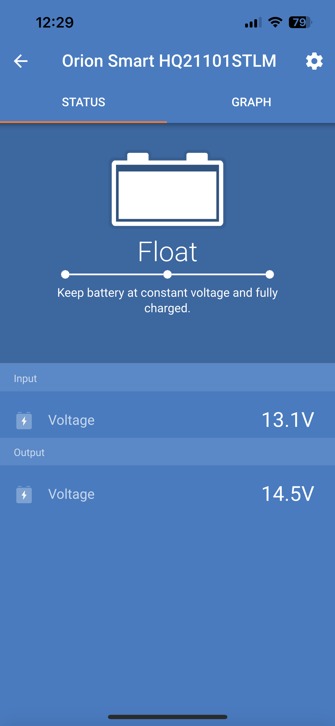
When your device has been loaded it will look something like this but somewhat different because it will be in “Power Supply” mode (see below to change)
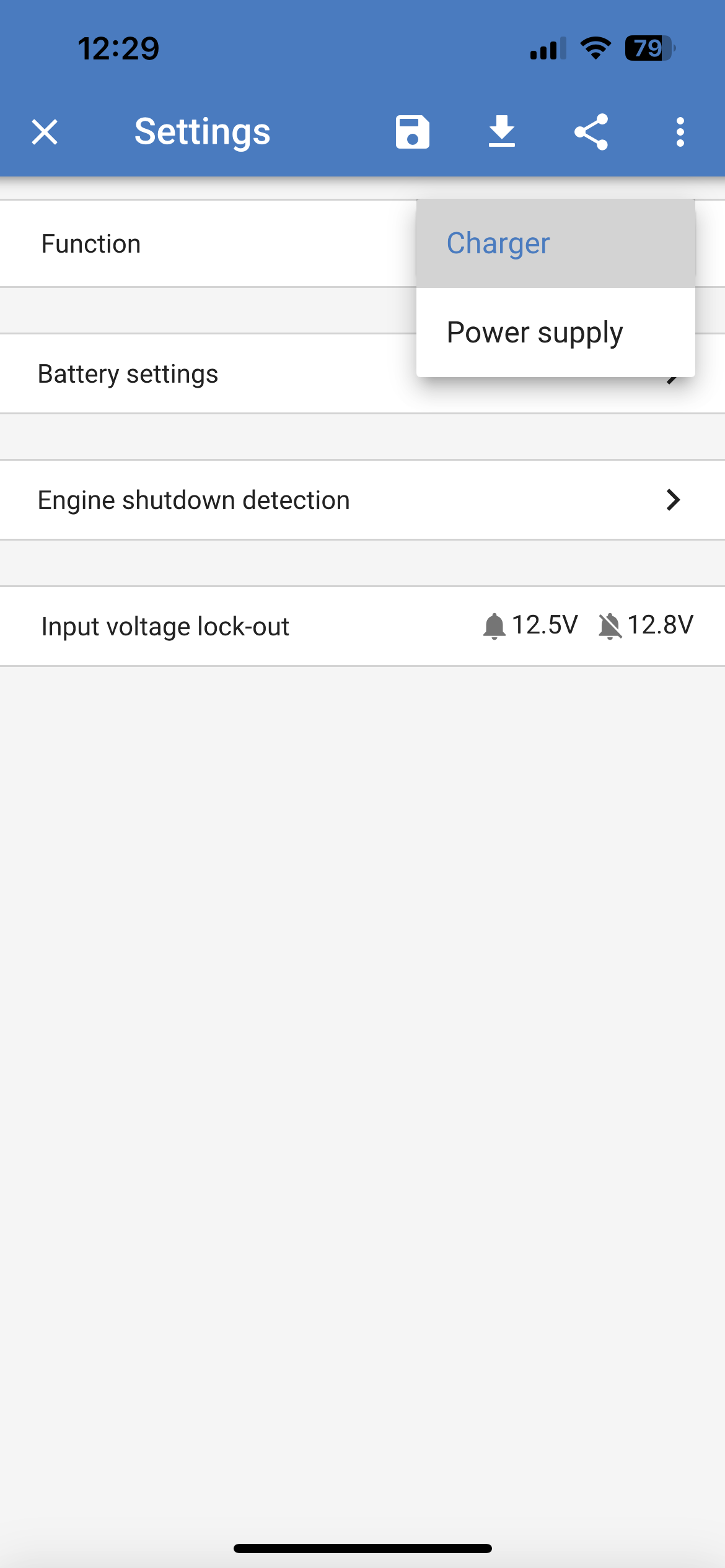
Click on the cog Top Right to get to Settings (next to the device name).
Once all the setup is complete and the battery is fully charged this is the screen we’d expect to see.
settings page
Once in Settings, change from “Power Supply” to “Charger”.
If you click the three dots (ellipsis) on the very Top Right side you will be able to change the device name as well as the PIN.
Go to Battery Settings when done.
battery settings
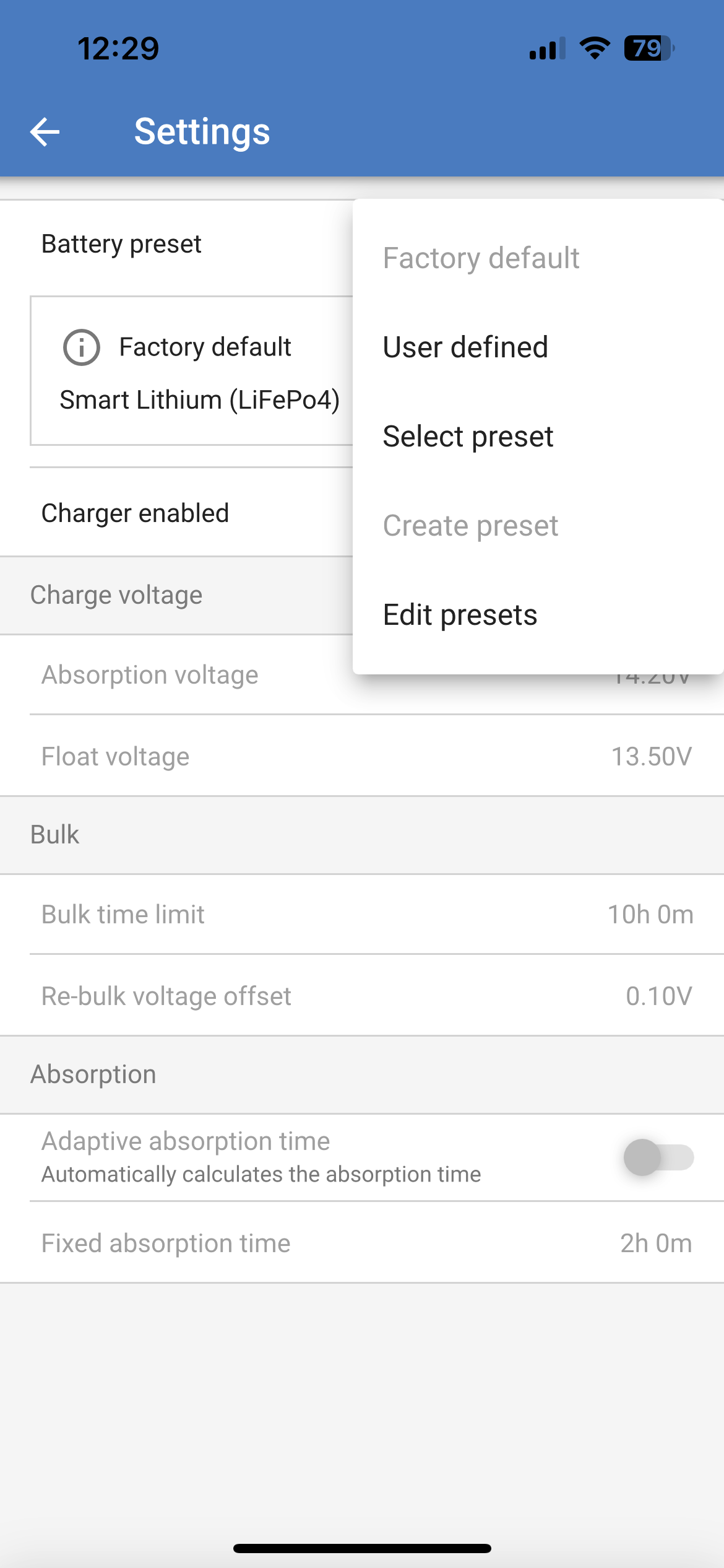
Assuming you have a LifePO4 battery, drop down on Factory Default.
choose your battery
Choose “Select preset”.
choose your battery type
Choose your battery type, LifePO4 is at the bottom of the list and you will need to scroll to get to it.
important for charger activation
Please refer to the section above for charger activation.
If you are using D+ activation you should specify a Start Voltage of 13, and the other parameters will adjust automatically.
Once you have changed the Start Voltage your alternator type should automatically change to Custom.
good default values
These are good default values. They protect your starter battery.
Component & Tool List
Here’s the list of components & tools that we would recommend for a DC to DC Charger installation:
Conclusion
Well, that concludes the installation of your DC-DC charger. We hope this article is of help to you, and we’d love to hear from you! If you have any questions or would like to get in touch with us about installing a DC to DC charger in your motorhome, please get in touch.


